Introduction
In 2018, a rigging operation fails in a landfill liner installation. The load wasn't the problem—the anchor stakes pulled free, sending a worker plunging 45 feet to his death. NIOSH investigations reveal that 68% of suspension scaffold incidents involve equipment failure, often traced not to overload but to improper anchor configuration, deteriorated components, or rigging angles that multiplied forces beyond safe limits.
These failures share a common root: improper anchor rigging. Anchor rigging is the foundation of every safe lifting, securing, and rescue operation.
While anchor points themselves—beams, trees, vehicles—might seem straightforward, the way you rig them determines whether your system holds or catastrophically fails. Proper anchor rigging accounts for angles, load distribution, rope selection, environmental hazards, and the physics of force multiplication.
This guide covers:
- Anchor rigging fundamentals and setup procedures
- Critical parameters like angles and rope types
- Common mistakes that lead to failure
- When to deploy specific techniques for industrial, marine, and rescue applications
Key Takeaways
- Bombproof anchors and proper technique are both essential—one without the other fails
- Keep anchor angles under 90° (maximum 120°)—beyond that, forces multiply dangerously
- Static rope (10-11mm) from established manufacturers ensures consistent load performance
- Always implement redundancy for life-safety applications—two independent anchors per person
- Failures typically stem from excessive angles, wrong rope, missing edge protection, or no redundancy
Understanding Anchor Rigging Fundamentals
Anchor rigging combines two elements: selecting a solid anchor point (the physical structure) and rigging it correctly (how rope or webbing connects the load to that point). Get either wrong and the system fails.
Three Primary Anchor Categories
A simple anchor uses a single point—acceptable only when that point is truly bombproof and the consequence of failure is low.
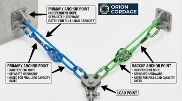
Backed-up anchors add an independent secondary anchor that engages if the primary fails, while multi-point anchor systems distribute load across two or more anchors, reducing force on each individual point.
Matching Configuration to Application
A static load suspended from a steel beam requires different rigging than a dynamic rescue load or a marine mooring application. Static loads are predictable; dynamic loads introduce shock forces that can double or triple the effective load.
Marine applications add corrosion, constant movement, and environmental degradation.
The Role of Rope Quality
High-quality rope designed for the specific application is non-negotiable. Static rope minimizes stretch for hauling and positioning systems; dynamic rope absorbs shock loads in fall protection.
NFPA 1983 sets minimum breaking strength at 20 kN (4,496 lbf) for Technical Use rope and 40 kN (8,992 lbf) for General Use.
When anchor systems carry life-safety loads, rope quality becomes paramount. Orion Cordage has manufactured industrial rope since 1856, providing the consistent quality and durability that anchor systems depend on. Domestically manufactured rope from established suppliers ensures consistent testing, quality control, and performance under load—critical factors when lives depend on the system.
The "Bombproof" Standard
"Bombproof" describes an anchor so robust its failure is inconceivable under expected loads. For life-safety applications, anchorages must support at least 5,000 lbs (22.2 kN) per person attached, or be designed by a qualified person with a minimum 2:1 safety factor.
The 20 kN minimum for rope and equipment provides a 10:1 safety margin even after accounting for knot strength reduction.
Step 1: Assess and Select Your Anchor Points
Survey your environment systematically to identify potential anchor points.
Options include structural elements (steel beams, concrete columns), natural features (large-diameter trees, solid boulders), vehicles (frame-mounted points, not bumpers or body panels), or installed anchors (certified bolts, plates, or dedicated anchor points).
Evaluate Structural Integrity
Once you've identified candidates, evaluate each potential anchor for:
- Load capacity – Does it meet the 5,000 lb minimum for personnel, or the calculated load for material handling?
- Deterioration – Rust, rot, stress cracks, loose fasteners, or weathering that compromises strength
- Structural soundness – Is the beam attached securely? Is the tree alive and rooted firmly?
Avoid corroded metal, weathered wood, loose bolts, or anything showing visible damage. According to NIOSH research, deterioration and improper installation cause more failures than simple overload.
Position Relative to Load
With structural integrity confirmed, consider anchor positioning.
Position anchors directly above or in-line with the direction of pull. Off-axis loading multiplies forces and can cause anchors to fail at loads well below their rated capacity.
Account for Environmental Hazards
Finally, scan for environmental hazards before rigging.
Identify sharp edges that could cut rope, heat sources (steam lines, hot pipes above 330°F) that degrade synthetic fibers, chemical exposure areas, or moving equipment that could contact the rigging. Address these before rigging, not after the system is loaded.
Step 2: Choose Your Rigging Configuration
Select your configuration based on anchor quality, load size, and consequence of failure.
Configuration Decision Tree
Simple anchor: A single bombproof point works for low-consequence applications like material handling or temporary securing.
Backed-up anchor: Add an independent secondary anchor for any life-safety application, even if the primary appears adequate.
The backup must be truly independent—separate anchor point, separate rope, separate hardware.
Multi-point system: Deploy when no single bombproof anchor exists, when load exceeds any single anchor's capacity, or when you need to distribute forces across a structure.
Critical Angle Management
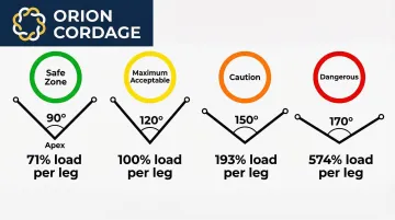
Once you've chosen a multi-point configuration, For multi-point systems, anchor angle is the single most critical parameter. Position anchors to create an interior angle of 90° or less at the focal point.
Force multiplication by angle:
| Angle Between Legs | Force on Each Leg |
|---|---|
| 90° | 71% of load |
| 120° | 100% of load |
| 150° | 193% of load |
| 170° | 574% of load |
At 120°, each anchor bears the full load—you've gained nothing from the multi-point system.
Beyond 120°, forces exceed the total load, and failure becomes likely even with adequate rope and anchors.
Select Rigging Materials
Rope selection by distance:
- Long anchors (5+ meters / 16+ feet back): Use three strands of 10-11mm static rope to reduce stretch and system movement
- Short anchors (under 5 meters / 16 feet): 8mm accessory cord or webbing may suffice depending on load and application
Static rope is essential for anchor systems. Dynamic rope's high stretch creates excessive movement and can shock-load the system when the load shifts.
Step 3: Rig and Secure the Anchor System
Attach rope or webbing using methods appropriate to the anchor type:
- Girth hitch for wrapped anchors (trees, pipes, beams)
- Basket configuration for load distribution around structural elements
- Direct connection through certified anchor hardware
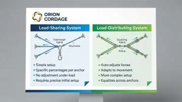
Load Sharing in Multi-Point Systems
When rigging multi-point systems, leg length determines load distribution:
- Shorter legs carry more load
- Longer legs carry less load
- Equal-length legs with centered focal point create balanced distribution
Adjust leg lengths deliberately based on anchor strength and intended load sharing.
Edge Protection is Mandatory
Install edge protection at every point where rope contacts sharp or abrasive surfaces. Even moderate edge radius can cut rope fibers under tension.
Use commercial edge rollers, padding, or protective sleeves. Never run rope over bare edges.
Pre-Tensioning for Long-Distance Rigging
For anchors positioned more than 5 meters back, pre-tensioning is essential:
- Set up a 3:1 mechanical advantage system
- Tension until lines are drum-tight
- Capture tension with friction hitches (7-8mm prusik cord on 10-11mm rope)
Pre-tensioning removes stretch and positions the focal point before loading.
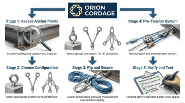
Step 4: Verify, Test, and Monitor
Visual Inspection Checklist
- All knots dressed and set properly
- Carabiners locked with gates oriented along the spine (not cross-loaded)
- No visible rope damage (cuts, glazing, excessive abrasion)
- Edge protection in place at all contact points
- Hardware rated for the application and properly installed
Verify Anchor Angles
Measure the angle at the focal point:
- If angle exceeds 90°, reposition anchors when possible
- Angles between 90-120° require verification that anchors and rope can handle 100% load on each leg
- Never proceed with angles exceeding 120° under any circumstances
Pre-Load Test
Gradually apply a portion of the expected load while monitoring for:
- Anchor movement or settling
- Rope slippage through knots or hardware
- System creep or gradual elongation
- Unexpected sounds (cracking, groaning, rope fibers breaking)
Continuous Monitoring
Once your system passes initial verification, monitoring shifts to active operations.
Assign dedicated personnel to watch anchor points and rigging throughout the work. Systems can degrade under load—what was secure at the start may not remain so. Immediate shutdown protocols should be established if any movement, slippage, or audible warning signs appear.
When Should You Use Advanced Anchor Rigging Techniques?
Advanced anchor rigging techniques become necessary when standard single-point anchors can't meet safety or performance requirements. Understanding when to deploy each technique protects personnel and ensures system reliability under demanding conditions.
Deploy multi-point anchor systems when:
- No single bombproof anchor exists at the site
- Load exceeds any single anchor's rated capacity
- Redundancy is required for high-consequence operations (rescue, personnel lifting, critical loads)
Use pre-tensioned back-tie systems when:
- Anchors are positioned more than 5 metres from the edge and you need to bring the focal point forward
- Rope stretch over distance would create unacceptable system movement under load
The most critical decision involves redundancy. Use backed-up anchor configurations for any application where anchor failure would result in injury or death, even if the primary anchor appears adequate. In rescue, fall protection, and personnel rigging with high-performance rope, redundancy is not optional—it's the baseline standard.
Critical Parameters That Affect Anchor Performance
Anchor Angle and Force Multiplication
As the angle between two anchor legs increases, force on each anchor increases dramatically. At 90°, each leg sees approximately 71% of the load. At 120°, each sees 100% of the load. Beyond 120°, forces rise exponentially—at 170°, each anchor bears nearly 600% of the load.
Guidance: Keep multi-point anchor angles at 90° or less. If angles reach 90-120°, verify anchors can handle 100% of the load before proceeding.
Never exceed 120°. This creates dangerous force multiplication that overloads even high-quality equipment.
Rope Type and Quality
Static rope has minimal stretch (6-10% elongation at 10% of breaking strength), making it ideal for anchor systems, hauling, and positioning.
Dynamic rope stretches significantly to absorb shock loads in fall protection but is unsuitable for anchor rigging due to excessive movement.
Rope quality matters critically. Look for domestically manufactured rope from established suppliers with consistent testing and quality control. Inferior rope can fail unexpectedly even when rigging technique is correct.
For life-safety applications, choose manufacturers with documented quality control and North American production standards.
Material Properties
Understanding material characteristics helps match rope to application conditions:
- Nylon — High strength and elasticity but loses ~15% strength when wet; vulnerable to acid damage
- Polyester — Lower stretch than nylon, retains strength when wet, better UV resistance; ideal for static applications
- Polypropylene — Floats but has low melting point (~330°F) and poor UV resistance; unsuitable for critical friction-based rigging
Load Distribution Method
Once you've selected appropriate materials, how you distribute load across anchors becomes critical.
Load-sharing systems adjust leg lengths to place specific load percentages on each anchor—simple but doesn't adjust if load shifts. Load-distributing systems use rigging that automatically adjusts to equalize forces—more complex but adapts to load movement.
Pre-tensioning removes stretch and positions the system before loading. Adjustable rigging allows repositioning under load but may introduce slack or shock loading if not managed carefully.
Environmental and Edge Factors
Sharp edges concentrate stress and cut rope fibers. Even rounded edges cause abrasion over time, especially under load or with movement. Edge protection is mandatory wherever rope contacts structural surfaces.
Temperature considerations: Synthetic rope loses strength when exposed to heat. Nylon melts at approximately 482°F; polypropylene at 330°F. Friction from ropes running over each other or through devices can generate enough heat to damage fibers.
Chemical exposure: Acids degrade nylon; alkalis affect polyester. Ropes exposed to unknown chemicals or exhaust fumes should be retired immediately.
Redundancy and Backup Systems
Redundancy means having independent backup that engages if the primary system fails—not just multiple connection points on the same anchor. OSHA requires two independent anchorages for rope descent systems, each capable of supporting 5,000 lbs per person.
Backed-up anchors must be truly independent: separate anchor points, separate rope or webbing, separate hardware. No single failure should compromise the entire system.
Common Mistakes in Anchor Rigging
Even experienced riggers can make critical errors that compromise system safety. Here are the most common mistakes to avoid:
Excessive anchor angles beyond 120° multiply forces exponentially, overloading anchors or rope that would otherwise handle the load. This is the most common rigging error and the easiest to prevent through proper geometry planning.
Wrong rope selection creates hidden dangers:
- Using dynamic rope in static applications (or vice versa)
- Undersized diameter for the load requirements
- Deteriorated rope or rope with unknown history
- Rope must be retired after 10 years regardless of appearance, or immediately if it shows physical damage, chemical contamination, or shock-loading
Neglecting edge protection at contact points leads to rope damage that compromises system strength. Edge damage causes progressive failure—the rope looks fine until it suddenly doesn't.
Skipping pre-tensioning on long spans allows excessive stretch when the load goes live, creating shock loads or dangerous slack that can drop the load unexpectedly.
Troubleshooting Anchor System Issues
Problem: Excessive rope stretch or system movement when load is applied
Check if you're using appropriate rope—static rope should show minimal stretch. If using static rope and still seeing excessive stretch, consider using multiple strands or pre-tensioning the system to reduce movement.
Common solutions include:
- Using multiple rope strands to distribute load
- Pre-tensioning the system before applying full load
- Verifying anchor points aren't shifting or settling
Structural anchors may flex; natural anchors may settle into soft ground. Reposition or add backing anchors if the primary anchor is moving.
Problem: Uneven load distribution in multi-point system
Inspect leg lengths and adjust so each anchor bears appropriate load. Shorter legs carry more load, while longer legs bear less weight.
For equal distribution, legs should be equal length with the focal point centred between anchors.
Verify anchor angles haven't shifted during loading and that the focal point is positioned correctly relative to the load direction. Off-axis loading can cause uneven distribution even with equal leg lengths.
Problem: Rope showing wear or damage at contact points
Immediately add edge protection (padding, rollers, or sleeves) at any point where rope contacts surfaces. Do not continue operations until edge protection is in place.
Inspect the rope thoroughly for fibre damage. Retire and replace if core fibres are visible or if outer sheath shows significant abrasion (more than 50% of sheath yarns damaged).
Never attempt to repair damaged life-safety rope.
Conclusion
Effective anchor rigging combines three elements: selecting appropriate anchor points, rigging them with correct angles and techniques, and using quality rope suited to the application. Most anchor system failures trace back to preventable mistakes—poor angle management, inadequate rope selection, skipped edge protection, or missing redundancy.
Anchor rigging is a learned skill requiring practice, ongoing training, and adherence to industry standards. Quality rope from proven manufacturers forms the foundation of any safe anchor system. With 168 years of rope manufacturing experience, Orion Cordage delivers the consistent quality and performance that professional rigging applications demand.
Frequently Asked Questions
What kind of rope is used for anchoring?
Static rope (low-stretch kernmantle construction, typically 10-11mm diameter) is standard for anchor systems in industrial and rescue applications, while dynamic rope is reserved for fall protection. Choose high-quality rope from established manufacturers for consistent performance.
What is the 3/2-1 anchoring system?
This refers to a redundancy principle: 3 points of contact, 2 independent anchors, 1 focal point. Specific anchor system design varies by application and should follow industry standards for your field.
What are the three types of rigging?
Simple rigging uses a single anchor point, backed-up rigging adds an independent backup anchor, and multi-point rigging distributes load across 2+ anchors. Selection depends on anchor quality, load magnitude, and consequence of failure.
What are the three types of anchors?
Natural anchors (trees, boulders), structural anchors (building elements, vehicles, beams), and installed anchors (bolts, plates, dedicated points) each require different assessment. Natural anchors need root stability checks, structural anchors need load capacity verification, and installed anchors need corrosion inspection.