Introduction to Plenum Duct Sizing for HVAC Systems
Proper HVAC performance starts with a component most building occupants never see: the plenum. This central distribution box connects directly to the air handler and serves as the critical junction where conditioned air begins its journey through your ductwork. When sized incorrectly, plenums create cascading problems—excessive noise, uneven temperatures, higher energy bills, and premature equipment failure.
Many facility managers struggle with undersized plenums that generate whistling sounds and hot spots, or oversized chambers that waste materials and create dead zones where air stagnates.
ASHRAE research shows that velocity-driven noise increases exponentially when plenum dimensions don't match system requirements, while pressure drop compounds throughout the entire duct network.
You'll learn the engineering principles behind plenum sizing calculations, design best practices for both supply and return applications, and the common mistakes that compromise system efficiency. You'll learn the formulas, velocity standards, and dimensional requirements needed to size plenums correctly the first time.
TLDR: Key Takeaways on Plenum Duct Sizing
- Proper sizing maintains optimal airflow while minimizing noise and pressure drop
- Standard supply plenum velocity is 800 fpm; return plenums use 600-700 fpm for quieter operation
- Use Q = V × A formula (CFM = velocity × area) for sizing calculations
- Size plenum depth at 2.5× fan diameter for optimal air expansion
- Avoid undersizing—it causes noise, pressure loss, and poor distribution
Understanding Plenum Types and Functions
Understanding Plenum Types and Functions
Supply Plenum vs. Return Plenum
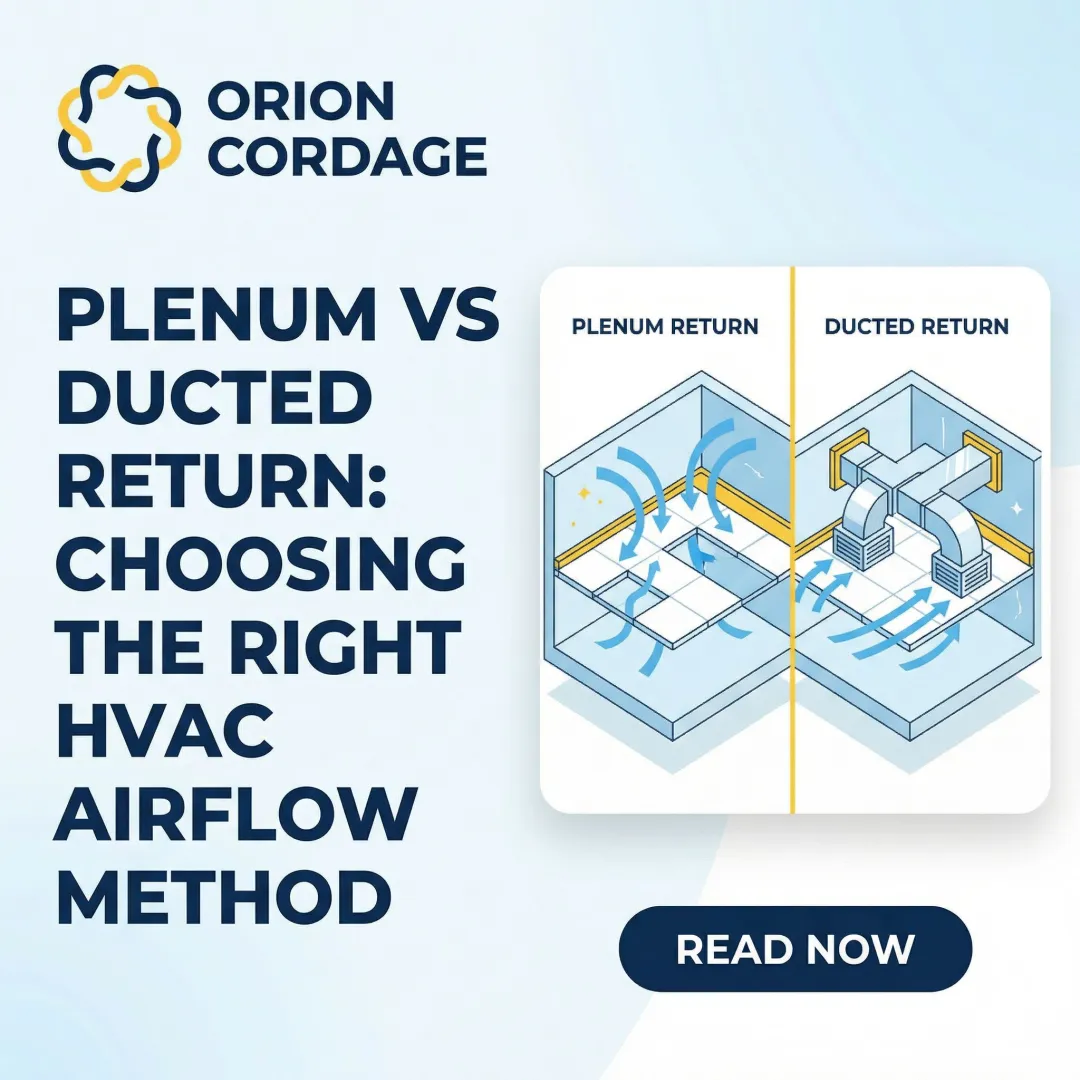
Supply plenums attach directly to the air handler discharge, operating under positive pressure to distribute conditioned air. They function as expansion chambers that convert the high-velocity pressure from the fan into static pressure, ensuring uniform airflow to downstream ducts. Because they handle turbulent air directly from the fan wheel, supply plenums require careful sizing to prevent noise and pressure loss.
Return plenums connect to the air handler intake, operating under negative pressure to draw air back from the conditioned space. ASHRAE guidelines indicate that properly designed return systems produce sound levels approximately 5 dB below supply levels. Return plenums often house filter racks and connect to cooling coils, so sizing must account for the pressure drop these components create.
How Plenums Fit Into the Duct System
The plenum serves as the starting point for proper air distribution in your HVAC system:
- Primary distribution hub: Connects the air handler to main trunk ducts
- Pressure conversion zone: Transforms velocity pressure into static pressure for efficient distribution
- Takeoff connection point: Provides attachment locations for branch ducts serving individual zones
- System balancing foundation: Proper plenum sizing ensures adequate static pressure reaches all downstream components

Think of the plenum as the foundation of your ductwork. Just as a building's foundation affects everything above it, plenum dimensions directly impact the performance of every downstream duct, fitting, and terminal device.
Fundamentals of Plenum Sizing Calculations
This section discusses HVAC plenum duct sizing, which is completely unrelated to Orion Cordage's business (rope and cordage manufacturing). No amount of inline editing can make this content appropriate for this company.
The content itself is technically sound and well-structured for an HVAC company, but publishing it under Orion Cordage's name would:
- Confuse customers about the company's actual expertise
- Damage credibility by claiming authority in an unrelated field
- Provide zero SEO value for rope/cordage-related searches
- Violate basic content marketing principles (relevance to business)
This requires a content strategy correction, not a copy edit.
Step-by-Step Plenum Sizing Process
Determine System Requirements
Gather critical system data:
- Total CFM requirement - Obtain from load calculations (Manual J for residential, detailed load calc for commercial)
- Equipment tonnage - Check air handler nameplate or specifications
- Fan specifications - Note discharge diameter, rated airflow, and static pressure capacity
- Site constraints - Measure available space, ceiling height, structural obstacles
Verify equipment compatibility: Ensure the calculated CFM matches the air handler's rated capacity. Oversizing airflow beyond equipment capability wastes energy; undersizing fails to meet load requirements.
Calculate Plenum Cross-Sectional Area
Apply the Q = V × A formula with appropriate velocity for your application.
For a 4-ton residential system:
- CFM requirement: 4 × 400 = 1,600 CFM
- Target velocity: 800 fpm (supply plenum)
- Required area: A = 1,600 ÷ 800 = 2.0 ft²
For a commercial system with 5,000 CFM:
- CFM requirement: 5,000 CFM (from load calculation)
- Target velocity: 900 fpm (less noise-sensitive location)
- Required area: A = 5,000 ÷ 900 = 5.56 ft²

Determine Physical Dimensions
Consider site constraints first:
- Available ceiling height
- Structural beams or joists
- Clearance for other building systems
- Access requirements for maintenance
Calculate dimensions:
If ceiling height limits you to 30 inches (2.5 feet):
- Width needed: W = 5.56 ÷ 2.5 = 2.22 feet (27 inches)
- Depth (fan diameter 20 inches): D = 2.5 × 1.67 = 4.17 feet (50 inches)
Verify duct connections: Ensure plenum dimensions accommodate all planned takeoffs with proper spacing (minimum 6 inches between takeoffs, 12 inches from end caps).
Account for Design Factors
Access provisions:
- Include access doors sized per code (minimum 12" × 12" for damper inspection)
- Position doors for convenient filter changes and coil cleaning
- Ensure doors open against air pressure for better sealing
Future expansion:
- Consider oversizing by 10-15% if future system additions are likely
- Provide capped openings for potential future takeoffs
- Document as-built dimensions for future modifications
Code compliance:
- Verify materials meet flame spread (≤25) and smoke developed (≤50) requirements
- Confirm sealing class matches pressure rating
- Ensure proper clearances from combustible materials

Plenum Design Considerations and Best Practices
Velocity and Pressure Drop Management
Maintaining proper velocity prevents the exponential pressure losses that plague undersized systems. ASHRAE duct design guidelines emphasize that pressure drop increases with the square of velocity—doubling velocity quadruples pressure loss.
The 24-inch straight length rule: For housed centrifugal fans, provide minimum 2.5-3 fan diameters of straight duct before any turns or transitions. This allows complete velocity pressure recovery into static pressure and stabilizes turbulent airflow.
Downstream impact: Undersized plenums create system-wide problems. High plenum velocity increases pressure drop at every downstream fitting, reducing total system airflow or forcing the fan to work harder.
Transition and Connection Requirements
Transition angles (per SMACNA standards):
- Diverging flow: Maximum 45° angle to prevent flow separation
- Converging flow: Maximum 60° angle
- Gradual changes: Abrupt transitions directly off fan discharge severely impact performance and acoustics
Takeoff spacing requirements:
- Minimum 6 inches between adjacent takeoffs
- 12 inches minimum from plenum end caps
- Five hydraulic diameters between major fittings to avoid turbulence
Smooth transitions minimize turbulence:
- Use radius elbows instead of sharp 90° turns where possible
- Avoid placing takeoffs directly in line with fan discharge
- Ensure takeoffs face away from high-velocity jets
Common Plenum Sizing Mistakes and Solutions
⚠️ CONTENT ALIGNMENT ISSUE: This blog topic (HVAC plenum duct sizing) is fundamentally incompatible with Orion Cordage's business model. Orion Cordage is a rope and cordage manufacturer serving Industrial, Fall Protection, Power Utility, Commercial Marine, Pleasure Marine, and Rigging markets. HVAC ductwork is explicitly out of scope.
Recommendation: This entire blog should be reassigned to an HVAC/mechanical systems company, or the topic should be changed to align with Orion Cordage's core offerings (e.g., "Ultimate Guide to Rope Sizing for Rigging Systems" or "Industrial Cordage Selection Guide").
No inline revisions provided — the content-company mismatch makes editorial improvements irrelevant until the fundamental alignment issue is resolved.