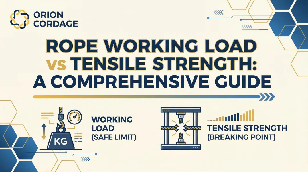
Introduction
A rigger prepares to lift a 5,000 lb transformer using a 2-leg bridle sling. The rope's tag shows 3,000 lbs capacity per leg—more than enough, right?
Not necessarily. The Working Load Limit (WLL) changes dramatically based on how the sling is rigged, and without proper calculation, this lift could end in catastrophic failure.
Understanding why this happens starts with North American safety standards.
WLL calculation is a fundamental requirement in rigging operations, governed by ASME B30.9 standards and enforced through OSHA (US) and CSA (Canada) regulations. According to OSHA investigations into rigging accidents, improper load rating and calculation errors remain leading causes of sling failures and workplace incidents.
The gap isn't in knowing a sling's rated capacity—it's in calculating the effective capacity based on specific lift parameters.
This article covers:
- What WLL is and why it matters
- Step-by-step calculation method
- Three critical variables: hitch type, sling angle, and D/d ratio
- Common calculation errors that compromise safety
Key Takeaways
- WLL is the maximum load a sling can safely handle in a specific configuration, always less than or equal to its rated capacity
- Hitch type, sling angle from horizontal, and D/d ratio directly reduce your sling's safe capacity
- Divide load by number of legs, then apply angle load factor (never use angles below 30°)
- Always start with manufacturer's rated capacity and de-rate for your configuration
- Calculate tension per leg by dividing load weight across legs, then multiply by your configuration's load factor
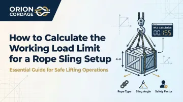
How to Calculate the Working Load Limit for a Rope Sling Setup
Step 1: Identify Your Sling's Rated Capacity and Hitch Type
Locate the sling identification tag showing the manufacturer's rated capacity for vertical, choker, and basket hitches. This is your starting baseline. ASME B30.9 standards require every sling to display manufacturer name, rated load for at least one hitch type, and the angle it's based on.
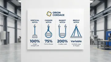
Hitch types and their capacity factors:
- Vertical hitch: 1.0 (100% of rated capacity) — single straight lift
- Choker hitch: 0.75 (75% of vertical rating) — sling forms a noose around load
- Basket hitch: 2.0 (200% of vertical rating) — sling cradles the load with vertical legs
- Bridle: Multiple legs at angles
Hitch selection has an immediate impact on capacity. A choker hitch reduces capacity to 75% of vertical rating, dropping further if the angle of choke is less than 120°.
True vertical basket hitches can double capacity, but only when legs are perfectly vertical and D/d ratio requirements are met.
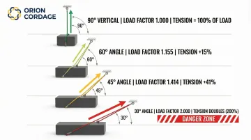
Step 2: Measure and Calculate the Sling Angle
Measure the vertical height (H) from the top of the load to the lifting hook, and the sling length (L) from hook to load attachment point. Calculate the sling angle using the H/L ratio or use a digital inclinometer for direct measurement. The angle is measured between the sling leg and a horizontal line.
Load factors for common angles:
| Angle from Horizontal | Load Factor | Tension Increase |
|---|---|---|
| 90° (Vertical) | 1.000 | 0% |
| 60° | 1.155 | 15.4% |
| 45° | 1.414 | 41.4% |
| 30° | 2.000 | 100% (doubles) |
As the angle decreases, tension on each leg increases dramatically. Industry data shows that at 30°, each leg must support tension equal to the entire load weight.
Verify that your sling angle is 30° or greater—angles below 30° are not allowed by ASME B30.9 without special engineering analysis.
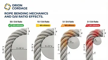
Step 3: Account for D/d Ratio (Diameter Effects)
The D/d ratio is the diameter of the object the sling bends around (D) divided by the rope diameter (d). Sharp bends reduce sling efficiency and strength.
D/d efficiency guidelines:
| D/d Ratio | Efficiency | Notes |
|---|---|---|
| 25:1 or higher | 100% | Required for full basket hitch rating |
| 15:1 | ~90% | Standard for hand-spliced slings |
| 5:1 | ~80% | Minimum for mechanically joined slings |
| Below 1:1 | Not recommended | Severe rope damage |
ASME B30.9 requirements mandate capacity reductions when D/d ratios fall below 15:1 for hand-tucked slings or 25:1 for mechanical splice slings.
Consult manufacturer charts for exact reduction percentages.
Step 4: Calculate Load per Leg and Compare to WLL
Divide the total load weight by the number of sling legs that will share the load. For 4-leg bridles, conservatively assume only 2-3 legs carry the full load unless verified by a qualified rigger.
Calculation formula:
Tension per leg = (Load Weight ÷ Number of Legs) × Load Factor
Example calculation: 4,000 lb load, 2-leg bridle at 45° angle
- Load per leg before angle factor: 4,000 ÷ 2 = 2,000 lbs
- Tension per leg after angle factor: 2,000 × 1.414 = 2,828 lbs
- Required sling capacity: Each leg must be rated for at least 2,828 lbs
Compare the calculated tension per leg to your sling's rated capacity (after applying hitch type and D/d adjustments). The tension must be less than the WLL. If it exceeds the WLL, the lift cannot proceed as planned.

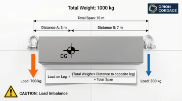
Step 5: Verify Centre of Gravity and Load Balance
Confirm that the lifting hook will be positioned directly above the load's centre of gravity before lifting. For asymmetric loads, calculate individual leg loads based on distance from centre of gravity:
Formula: Load on leg = (Total weight × Distance to opposite leg) ÷ (Total distance between legs)
Perform a trial lift 6 inches off the ground to verify the load is balanced and slings are not slipping before proceeding with the full lift. If the load tilts or slings shift, reposition the rigging and recalculate.
When Should You Calculate WLL for Your Sling Setup?
Knowing when to calculate WLL prevents both over-caution (wasting time on simple lifts) and under-preparation (risking safety). WLL calculation is mandatory before every lift where slings are used at an angle, with multiple legs, in choker configuration, or with loads over 1,000 lbs.
Situations requiring calculation:
- Multi-leg bridle hitches with any angle from vertical
- Angled basket hitches (legs not perfectly vertical)
- Loads with off-centre centers of gravity
- Lifts using small-diameter attachment hardware (low D/d ratios)
- Any lift where the sling tag's rated capacity doesn't directly apply
Scenarios where you may skip calculation:
- Single vertical hitch lifts well below rated capacity (under 50% WLL)
- Repetitive lifts with documented, approved lift plans
- Lifts using pre-engineered rigging with certified capacity charts
Even in these situations, a competent person must verify that conditions match the documented parameters before proceeding.
What You Need Before Calculating WLL for Your Sling Setup
Correct WLL calculation starts with proper preparation. You need accurate measurements, current documentation, and the right reference materials.
Equipment and Measurements Required
Essential documentation:
- Sling ID tags with rated capacities for each hitch type
- Manufacturer specification sheets if tags are missing or illegible
- Current inspection records confirming no capacity-reducing damage
Measurement tools:
- Measuring tape or digital inclinometer for sling angles and geometry
- Accurate load weight (from drawings, scale, or calculation)
- Centre of gravity location documentation
Reference materials:
- Manufacturer capacity charts with load factors for different angles
- D/d efficiency tables for bend radius calculations
- ASME B30.9 standards and OSHA 1910.184 regulations
Having the right tools and documentation is only part of the equation. The people performing these calculations must also meet specific training and compliance standards.
Knowledge and Compliance Requirements
Your rigging team must include trained personnel who can identify sling types, read capacity charts, and perform field calculations. OSHA 1910.184 requires that workers handling slings understand proper use, inspection, and load rating.
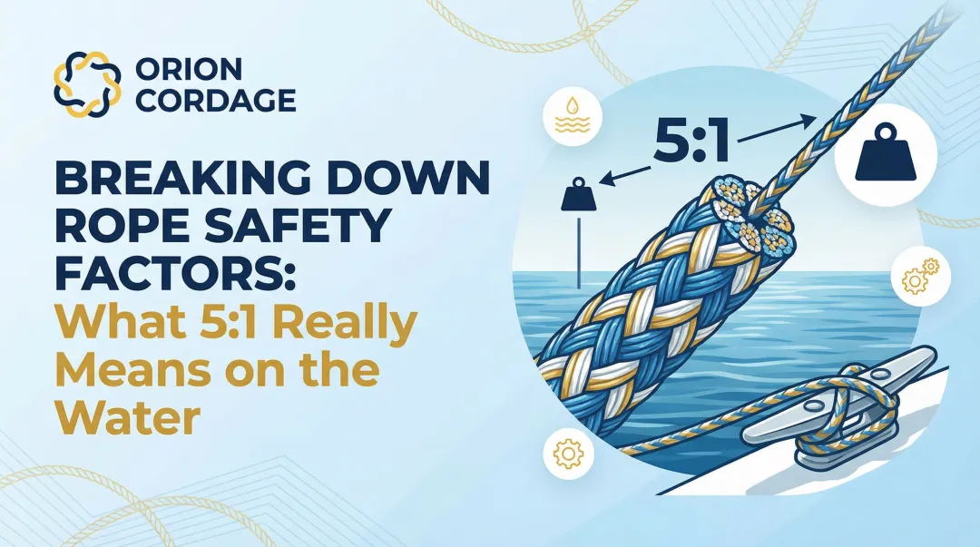
Understanding of ASME B30.9 standards for sling use ensures compliance with the minimum design factor of 5:1 for all wire rope slings. This means the breaking strength must be at least five times the rated WLL to provide proper safety margin.
Key Parameters That Affect WLL in Rope Sling Setups
Calculating working load limits isn't just about knowing your sling's rated capacity. Three primary variables—hitch type, sling angle, and D/d ratio—determine how much of that capacity can be safely used in any specific rigging configuration.
Hitch Type and Configuration Factor
The hitch you choose determines how forces distribute through the sling body and whether stress concentrations occur.
Capacity factors by hitch type:
- Vertical hitch = 100% of rated capacity (factor: 1.0)
- Choker hitch = 75% of rated capacity (factor: 0.75) when angle of choke is 120° or greater
- Basket hitch = 200% of rated capacity (factor: 2.0) for vertical legs only
In choker hitches, the sling passes through its own eye, creating stress concentrations that reduce capacity. The tighter the choke angle, the greater the reduction.
According to wire rope sling specifications, a choke angle below 30° reduces capacity to just 49% of the standard choker rating.
Sling Angle from Horizontal
As sling angle decreases from 90° (vertical), the load factor increases dramatically. At 60°, the factor is 1.155. At 45°, it jumps to 1.414. At 30°, it doubles to 2.000.
Low sling angles create high horizontal forces that dramatically increase tension in each sling leg. These horizontal forces can also cause the load to compress or buckle.
Research data confirms that angles below 30° can double or triple the load on each sling leg compared to vertical lifts, explaining why they're prohibited without special engineering approval.
D/d Ratio (Bend Severity)
Sharp bends reduce rope efficiency dramatically. A D/d ratio of 2:1 can cut sling strength by 40%, while a ratio of 20:1 or higher maintains approximately 100% efficiency.
Tight bends create uneven stress distribution across rope strands, with outer strands stretched and inner strands compressed. This leads to premature failure and permanent rope damage.
According to D/d ratio guidelines, ratios should be 20:1 or higher for full capacity, with mandatory de-rating for smaller ratios.
Number of Sling Legs and Load Distribution
While a 4-leg bridle theoretically shares load across four legs, ASME B30.9 standards state that "the rated load of a quadruple-leg or double-basket sling shall not exceed the rated load of a triple-leg sling."
Assuming equal load distribution across all legs can lead to individual leg overload if one leg is shorter or the load shifts during lifting. Industry practice assumes only 2-3 legs carry the full load due to unequal lengths or load geometry.
Conservative calculation approach:
- 2-leg bridles: Divide load by 2
- 3-leg bridles: Divide load by 2 or 3
- 4-leg bridles: Divide load by 2 or 3 (not 4) unless verified by qualified rigger
Load Weight and Centre of Gravity Position
Beyond how many legs carry the load, where the load's weight sits matters just as much. Off-centre loads create unequal forces on sling legs, with the leg closest to centre of gravity carrying more weight than legs farther away.
This imbalance can overload one sling leg while others are underutilised, and the load will tilt during lifting if not properly balanced.
Formula for off-centre loads: Load on leg = (Total Weight × Distance to opposite attachment) ÷ (Total span between attachments)
This calculation ensures the most heavily loaded leg doesn't exceed its WLL, even when the load is asymmetric.
Common Mistakes When Calculating WLL for Rope Sling Setups
Even experienced riggers make calculation errors that compromise safety. Watch for these four critical mistakes:
Ignoring sling angle effects Assuming each leg carries half the load without applying angle load factors results in 50-100% underestimation of actual leg tension. This is the most common and dangerous calculation error in multi-leg setups.
Using damaged or worn slings Operating slings with visible wear, broken wires, or illegible identification tags without adjusting for reduced capacity puts operators at risk. ASME B30.9 requires immediate removal from service of slings with 10 randomly distributed broken wires in one rope lay.
Miscounting active load-bearing legs Assuming all 4 legs in a bridle configuration share load equally ignores real-world load distribution. Riggers must also account for D/d ratio reductions when using small-diameter shackles or hooks.
Estimating instead of measuring load weight Guessing load weight instead of calculating accurately leads to undersized slings. Failing to account for dynamic loading from sudden starts, stops, or swinging compounds the problem—dynamic forces can spike tension by 1.5x to 2.0x the static weight.
Troubleshooting Issues During WLL Calculation for Rope Sling Setups
Field conditions often present challenges that complicate straightforward WLL calculation, requiring problem-solving and conservative safety margins. The following scenarios address common measurement and documentation issues riggers encounter during setup.
Problem: Sling Angle Cannot Be Accurately Measured
Likely cause: Obstruction of measurement points, inability to access top of load, or complex rigging geometry.
What to do:
- Apply the h/l ratio method (measure a portion of the sling and corresponding vertical drop)
- Use a digital inclinometer app on a smartphone
- Assume the worst-case (smallest) angle and calculate conservatively
- Add 10-15% safety margin to account for measurement uncertainty
Problem: Load Weight Is Unknown or Uncertain
Likely cause: No engineering documentation available, load consists of mixed materials, or scale weighing is not feasible.
What to do:
- Calculate weight from material density and volume
- Use conservative estimates and add 20% safety margin
- Consult with engineers or manufacturer for component weights
- Contact equipment manufacturers for certified weights on transformers and specialized loads
Problem: Sling Tag Is Missing or Illegible
Likely cause: Sling has been in service for extended period, tag damaged during use, or sling is of unknown origin.
What to do: Remove sling from service immediately per ASME B30.9 requirements. If manufacturer and specifications can be verified through documentation, obtain replacement capacity information before use.
Never estimate or guess a sling's rated capacity.
Alternatives to Manual WLL Calculation for Rope Sling Setups
While manual calculation is the standard method, several tools and approaches can simplify the process or provide additional safety margins.
Digital Rigging Calculators and Mobile Apps
Best for: Field verification, smartphone-equipped riggers, or rapid multiple calculations.
Industry-standard tools:
- Crosby Group Rigging Calculator: Available as app and physical slide rule, validates calculations against ASME B30.9 standards
- Northern Strands Sling Tension Calculator: Web-based tool for 2-leg and 3-leg bridles, including off-center center of gravity scenarios
- Lift-All Sling Calculator: Assists in selecting appropriate sling sizes and lengths for specific applications
Important limitations:
- Require accurate input data and understanding of underlying principles
- May not account for dynamic loading or environmental factors
- Always verify results against manufacturer charts
Pre-Engineered Lift Plans and Manufacturer Charts
Best for: Repetitive lifts with consistent loads and configurations, or standardized rigging equipment with certified capacity documentation.
Important limitations:
- Less flexibility for non-standard lifts
- Requires strict adherence to documented procedures
- Any deviation from documented configuration requires recalculation
Professional Rigging Engineering Services
Best for: Complex lifts, critical lifts over certain tonnage, unusual geometry, or sling angles below 30°.
Important considerations:
- Additional cost and time for engineering analysis
- Provides maximum safety assurance and liability protection
- Essential for lifts exceeding 75-80% of crane or sling capacity
For complex lifting scenarios, consider consulting with experienced rope and rigging manufacturers.
Orion Cordage, with over 150 years of manufacturing expertise, provides guidance on proper sling selection and rigging configurations for demanding industrial applications.
Conclusion
Calculating WLL for rope sling setups requires understanding three critical factors: hitch type, sling angle, and D/d ratio. Sling angle is the most commonly miscalculated parameter, with errors leading to leg tensions double or triple what riggers expect.
These calculations aren't just best practice—they're legal and safety requirements under ASME B30.9 and OSHA standards. Conservative assumptions should always be made when uncertainty exists.
For reliable results, start with quality rope slings from established manufacturers with proven engineering expertise. Orion Cordage has manufactured industrial rope and cordage solutions since 1856, with products designed, tested, and manufactured in North American facilities. For complex lifts, consult with rigging professionals.
The rated capacity on a sling tag is just the starting point. Your job is to calculate the effective WLL for your specific rigging configuration, accounting for every factor that reduces that capacity.
When in doubt, use a larger sling, improve the geometry, or consult an expert. Safety margins exist for a reason.
Frequently Asked Questions
What is the minimum safe sling angle for rope sling lifts?
The industry standard minimum is 30° from horizontal per ASME B30.9. At 30°, each leg supports tension equal to the entire load weight. Operations below 30° require special engineering approval.
Can I use a rope sling if the identification tag is missing?
No. ASME B30.9 requires immediate removal from service of any sling with missing or illegible identification, as the rated capacity cannot be verified. Never estimate or guess a sling's capacity—this is a leading cause of rigging failures.
How do I calculate WLL for a 4-leg bridle sling?
Divide the load by 2 or 3 legs (not 4) to account for unequal distribution, apply the angle load factor, and verify each leg's tension stays below rated capacity. ASME B30.9 states 4-leg slings have no greater capacity than 3-leg slings.
What is a D/d ratio and why does it matter for WLL?
D/d is the ratio of bend diameter to rope diameter. Ratios below 20:1 require capacity de-rating—a 2:1 ratio can reduce strength by 40%, while 25:1 or higher maintains full capacity.
Do I need to recalculate WLL for every lift?
Yes, whenever rigging configuration changes—different angle, hitch type, or load weight. Repetitive identical lifts can use documented lift plans a qualified person has approved, eliminating recalculation if conditions match exactly.
What should I do if my calculated WLL is less than my load weight?
The lift cannot proceed as planned. Use larger capacity slings, increase the sling angle, add more legs, or employ a spreader bar. Never exceed calculated WLL—find a safer rigging configuration.